Physics of Ultrasound Ultrasound Imaging and Artifacts รศ.นพ.เดโช จ กราพาน ชก ล สาขาหท ยว ทยา, ภาคว ชาอาย รศาสตร คณะแพทยศาสตร ศ ร ราชพยาบาล
|
|
|
- Norma Williams
- 6 years ago
- Views:
Transcription


1 Physics of Ultrasound Ultrasound Imaging and Artifacts รศ.นพ.เดโช จ กราพาน ชก ล สาขาหท ยว ทยา, ภาคว ชาอาย รศาสตร คณะแพทยศาสตร ศ ร ราชพยาบาล


2 Diagnosis TTE TEE ICE 3D 4D Evaluation of Cardiac Anatomy Hemodynamic Assessment Multidimensional Echocardiography
3 Ultrasound Physics
4 Wave Motion VS Circular Motion
5 Ultrasound Waves Diagnostic medical ultrasound typically uses transducers with a frequency between 1-20 MHz Humans can hear sound waves with frequencies between 20 Hz and 20 KHz Adult echocardiogram: 2-4 MHz Pediatric echocardiogram: 4-8 MHz
6 Frequency One hertz (Hz) = One cycle per second Frequency (f) time = number of cycles Frequency (f) 1 period = 1 cycle 1 cycle Period ( ) Time Frequency (f) = 1 period
7 Wavelength Wavelength (λ) times frequency (f) equals the propagation velocity (c): c f Propagation velocity in the heart is 1540 m/s, the wavelength for any transducer frequency can be calculated as 1.54 (mm) f (MHz)
8
 Expanded Compressed (high pressure) Expanded")

9 Interaction with Tissue: Speed of Sound Compressed (high pressure) Expanded Compressed (high pressure) Expanded Distance As sound travels through tissue it compresses and expands the tissue. Where the tissue is compressed, the speed of sound is higher.


10 Nonlinear Propagation Compressed (high pressure) Expanded Compressed (hight pressure) Expanded Higher pressure portions of the wave travel faster Distance As the wave passes through tissue, the top of the waveform gets pulled forward to be non sinusoidal shape. Propagation in which speed depends on pressure and the wave shape changes is called nonlinear propagation. Harmonic frequency is generated from this nonlinear propagation.


11 Harmonic Imaging Increasing Depth Near Field No harmonics being generated Signal has not traveled enough to be distorted Near Mid Field Harmonics Increasing Harmonics beginning to be produced as signal travels through tissue Mid Field Harmonics Unchanging Additional harmonics generated and attenuated in equal proportion Far Mid Field Harmonics Decreasing Harmonics being attenuated faster than being produced Far Field Fundamental Frequency Only Maximum Harmonic Effect
 Expanded Distance")

12 Constructive Interference Compressed (high pressure) Expanded Compressed (high pressure) Expanded Distance The waves are in phase with each other. The waves reinforce each other, resulting in an intensified sound.


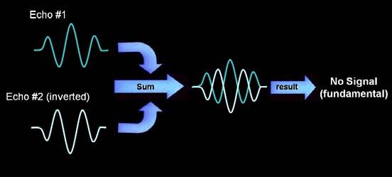
13 Destructive Interference Distance The waves are out of phase with each other. The waves cancel each other, resulting in a diminished sound.

")

 Fundamental")
14 Harmonic Signal Fundamental ultrasound signals are generated from the transducer passing the fat layer twice (transmit and receive) Harmonic signals are generated from the tissue and transmitted to transducer passing through the fat layer once (on receive) Fundamental signal Harmonic signal


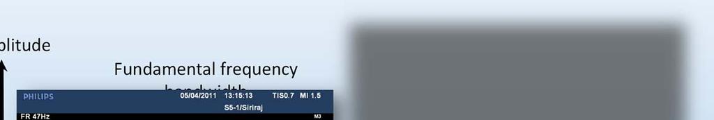
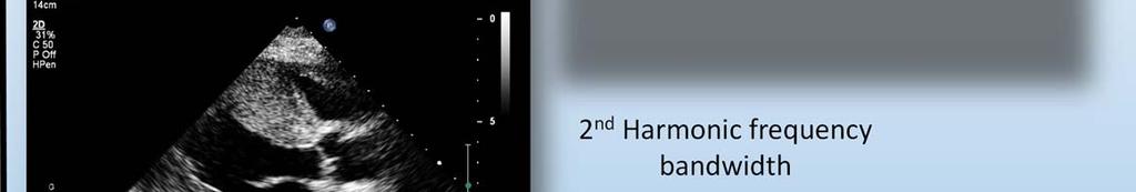
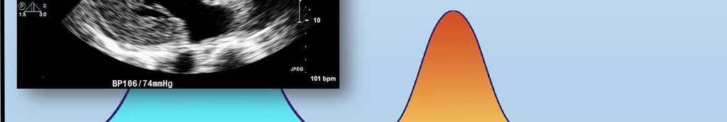
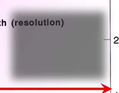
15 Harmonic Imaging Amplitude Fundamental frequency bandwidth 2 nd Harmonic frequency bandwidth f 0 2f 0 (Velocity)

 result in")
16 Ultrasound-Tissue Interaction Scatter Reflection Moving RBC Refraction Attenuation Specular reflector Small structures (< 1 wavelength in lateral dimension) result in scattering
17 Biologic Effect of Ultrasound
18 Medical Ultrasound Safety: Adverse Biological Effects Thermal bioeffects Heating of soft tissue and bone Nonthermal bioeffects Cavitation
19 Thermal Index (TI) The ratio of attenuated acoustic power at a specified point to the attenuated acoustic power required to raise the temperature at that point in a specific tissue model by 1 C TIB: Bone thermal index TIC: Cranial-bone thermal index TIS: Soft tissue thermal index
20 Acoustic Output Limits Non-ophthalmic applications I spta mw/cm 2 MI 1.9 TI 6.0 Ophthalmic applications I spta.3 50 mw/cm 2 MI 0.23 TI 1.0
21 Mechanical Index (MI) Mechanical bioeffects that occur when a certain level of output is exceed Mechanical index (MI) = Peak negative pressure Frequency
 Cranial bone (TIC) Mechanical index (MI) Range 0.")
22 Output Display Thermal index (TI) Soft tissue (TIS) Bone (TIB) Cranial bone (TIC) Mechanical index (MI) Range 0.0 to 1.9
23 Acoustic Impedance (Z) Measure of how ultrasound traverses the medium and depends on Density of the medium (p) Propagation velocity of ultrasound through the medium (v) Z = pv

24 Acoustic Impedance Fluid Soft tissue Fibrous tissue Solid (calcium)
25 Applied Ultrasound
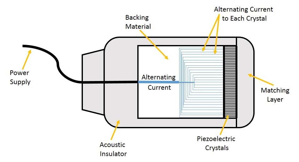
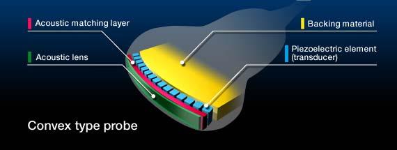
26 Ultrasound Transducer Device that converts a signal in one form of energy to another form of energy Mechanical rotating transducer (single element) Electronic phased array transducer (multiple elements) Linear array Annular array Matrix array Circular array Curved array

27 Piezoelectric Effect Piezoelectric element Piezoelectric element Direct piezoelectric effect, also called generator or sensor effect, converts mechanical energy into electrical energy. Mechanical stress generates an electric charge proportional to that stress. Inverse piezoelectric effect converts electrical energy into mechanical energy. Electrical voltage causes a change in length or vibration of piezoelectric material to generate a sound wave.

28 Transducer With 20 PZT Elements Piezoelectric elements
29 Transducer Mechanical annular array Electronic phased array
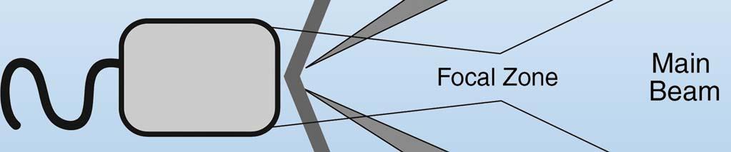
30 Ultrasound Beam Side lobe Side lobes Main lobe Main lobe


31 Ultrasound Beam (RadioGraphics 2009; 29: )
32 Side Lobes Secondary and smaller acoustic beams falling outside at predictable angle located around the main lobe Created by a single crystal transducer

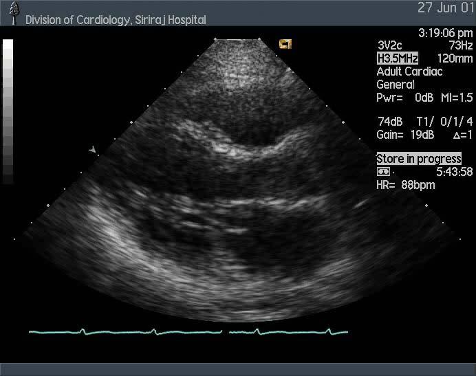
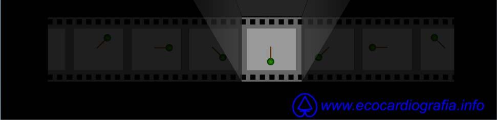
33 Ultrasound Images Motion mode Brightness mode Amplitude mode


34 Ultrasound Images Motion mode Brightness mode Amplitude mode
35 Creating a Two-dimensional Image Ultrasound beam is electronically steered through a sector arc of 80 Speed of imaging rate of 25 frames/s.
36 Creating a Two-dimensional Image The time needed to acquire all the data for one image frame is directly related to the number of scan lines There is tradeoff between scan line density and image frame rate

37 Depth VS Time elapsed Timing is proportional to distance from the transducer
38 Resolution The ability to distinguish two objects that are close together Temporal resolution The ability to accurately locate structures or events at a particular instant in time Spatial resolution Axial resolution: the ability to distinguish two objects that are close together along the axis of the ultrasound beam Lateral resolution: in the direction perpendicular to the beam s axis
39 Temporal Resolution Dependent on frame rate Can be improved by Minimizing depth - the maximum distance from the transducer as this affects the PRF Narrowing the sector to the area of interest - narrowing the sector angle Minimize line density (but at the expense of lateral resolution)
40 Axial Resolution The ability to recognize two different objects at slightly different depths from the transducer along the axis of the ultrasound beam 2 where SPL = λ no. of cycles It is improved by Higher frequency (shorter wavelength) transducers but at the expense of penetration Maximize line density (at the expense of frame rate, i.e. temporal resolution)

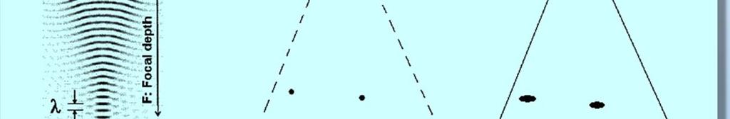

41 Lateral Resolution Lateral resolution = F D
42 Ultrasound Imaging

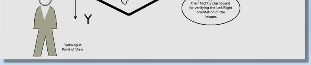
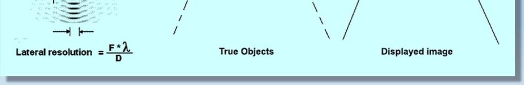
43 Medical Image Orientation
44 Gain Control The degree of amplification of the returning ultrasound signal Affects all parts of the image equally Seen as a change in brightness of the images on the entire screen
 Depth Signal")
45 Time Gain Compensation (TGC) Depth Signal Amplitude


46 Reject Filters out low signal decrease noise in the image No reject High reject
47 Dynamic Range (Compression) Determines the number of gray shades used to map the gray scale image on the display Higher more shades of gray (softer looking image) Lower fewer shades of gray (sharp looking image)


48 Wide Dynamic Range


49 Narrow Dynamic Range

50 High Compression

51 Low Compression

52 Harmonic Imaging
53 Type of Doppler Study Pulse wave Doppler Doppler information is generated from a small gate that is interrogated Continuous wave Doppler One crystal constantly sends, another constantly receives Allows evaluation of very high velocity
54
55 Color flow Doppler This is a variety of pulse wave Doppler. Multiple points in the region of interest are analysed and colour coded rapidly.
56 Doppler Filter Doppler signal from tissue VS blood Blood flow has low amplitude but high frequency Myocardial motion has high amplitude but low frequency High pass filter (Wall filter) Remove low frequency signals from the display Display Doppler signal from blood flow only Low pass filter Remove high frequency signals from the display Display Doppler signal from tissue only


57 Doppler of Blood Amplitude High Pass Filter Tissue Blood Frequency (Velocity)

58 Doppler of Tissue Amplitude Low Pass Filter Tissue Blood Frequency (Velocity)
59 Doppler Filter Amplitude Transitional zone Pass Pass Boost Pass band Pass band Boost Cut Cut Low Pass Filter High Pass Filter (Wall Filter) Frequency
60 High Pass Filter (Wall Filter) Amplitude Transitional zone Pass Boost Cut Pass band Boost Cut Low Pass Filter High Pass Filter (Wall Filter) Frequency
61 Low Pass Filter Amplitude Transitional zone Pass Boost Pass band Cut Low Pass Filter Frequency
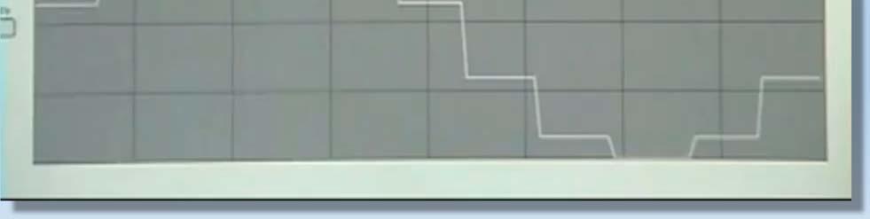
62 Doppler Display The perceived returning frequency is lower than the transmitted frequency, it will be plotted below the zero baseline as a negative Doppler shift The spectrum displays echo amplitude by varying the brightness of the display
63 Spectral Display Frequency Low amplitude Time
64 Spectral Display Frequency Mid amplitude Time
65 Spectral Display Frequency High amplitude Time
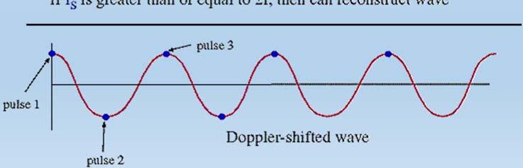
66 Sampling of Received Doppler Signal

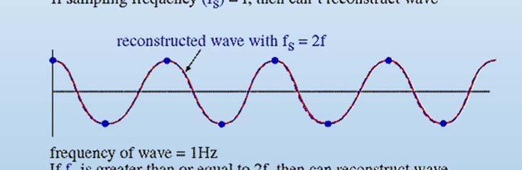


67 Sampling Frequency
68


69 Aliasing
70 Aliasing of Doppler Signal Erroneous display of velocities that have exceeded the Nyquist limit The velocity exceeds the rate at which the pulsed wave system can record it properly Spectral trace is cut-off at a given velocity with placement of the cut section in the opposite channel or reverse flow direction
 will be appropriately displayed only if the pulse")
 encountered in the")
71 Nyquist Frequency Measurements of frequency shifts (and, thus, velocity) will be appropriately displayed only if the pulse repetition frequency (PRF) is at least twice the maximum velocity (or Doppler shift frequency) encountered in the sample volume
72 The Nyquist Limit A sampled waveform thus needs at least two sample points per cycle. Thus the wave's frequency must not be above half the sampling frequency. This limit is called the Nyquist limit of a given sampling frequency
73 Basic Assumption Used in Imaging Systems 1. Sound travels in a straight line 2. Sound travels directly to a reflector and back 3. Sound travels in soft tissue at exactly 1540 m/s 4. Reflections arise only from structure positioned in the beam s main axis 5. The imaging plane is very thin 6. The strength of a reflection is related to the characteristics of the tissue creating the reflection (Understanding Ultrasound Physics. Sidney K Edelman, 4 th ed 2012)
74 Artifacts Caused by violation of the assumptions Direction Ultrasound path between transducer and reflector is not in straight line Transmit path Receive path Reflection Reflection from side lobe ultrasound beam Speed is not correct Attenuation
75 Artifacts due to Direction of Ultrasound
76 Refraction
77 Mirror Image

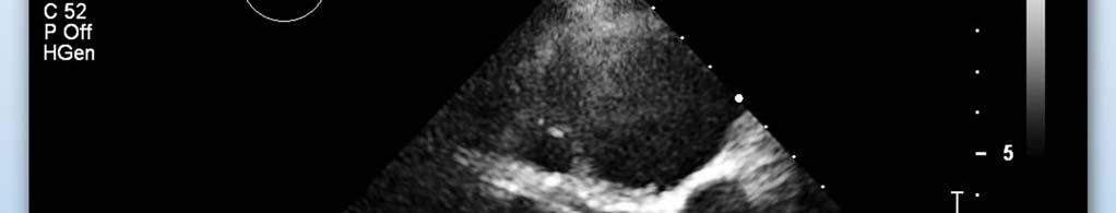
78 Reverberation A is the true anatomical structure strongly reflective of ultrasound A1 is the artefact generated by the returning ultrasound beam being re-reflected from the transducer and again reflected from the true anatomical structure at A. As this doubly reflected beam has travelled twice as far it is seen at twice the distance from the transducer. It is weaker but otherwise identical to the real structure at A A A1
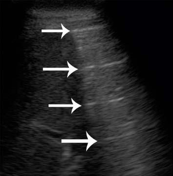
79 Reverberation
80 Reverberation
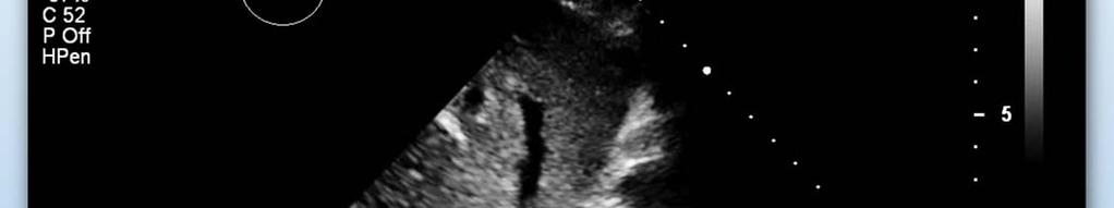
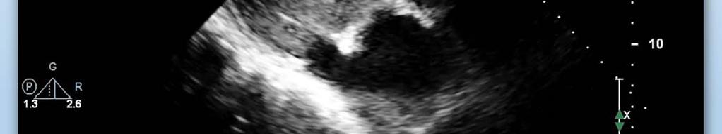
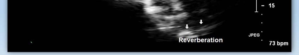
81 Reverberation
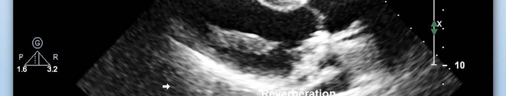
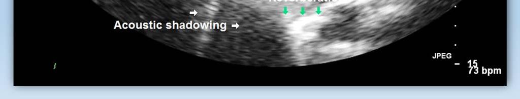
82 Reverberation and Shadowing
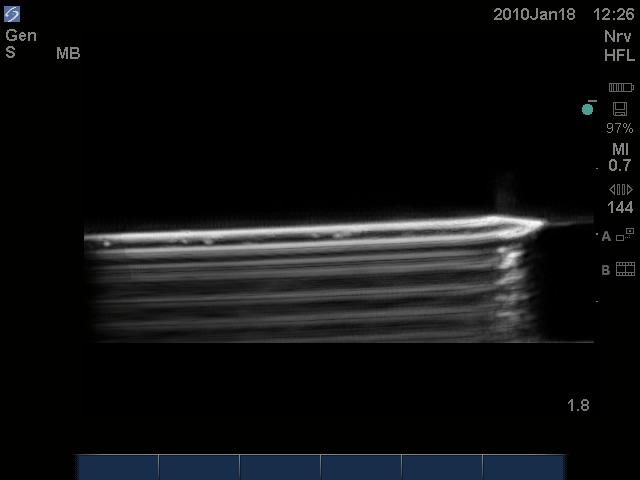
83 Comet Tail (Ring Down Artifact) Reverberation with the spaces squeezed The reflecting surfaces are located in a medium with a very high propagation speed, such as mechanical heart valve Appearance of solid hyperechoic line directed downward
84 Comet Tail (Ring Down Artifact)


85 Comet Tail (Ring Down Artifact)


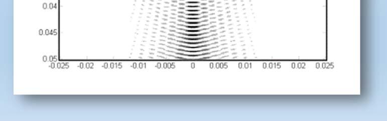
86 Ultrasound Beam Side lobes Main lobe (RadioGraphics 2009; 29: )
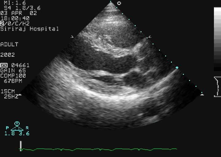
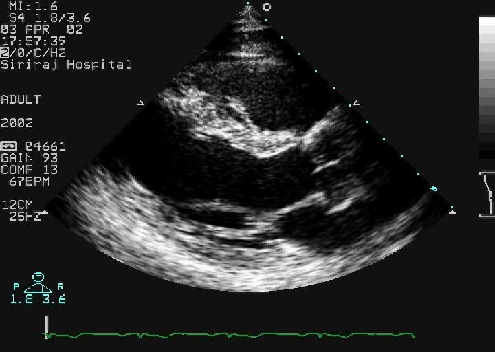
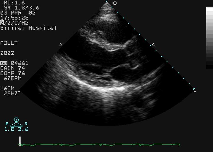
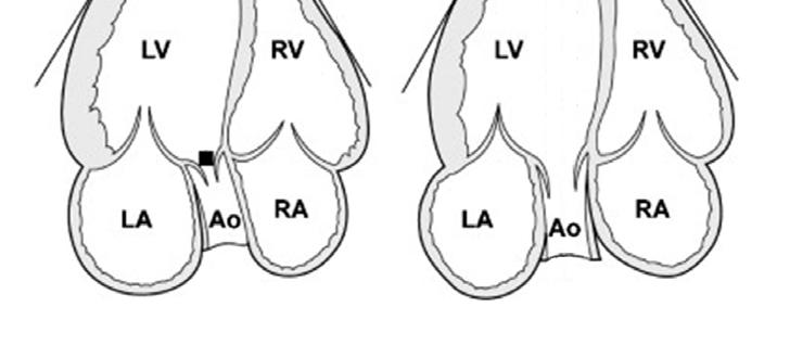
87 Side Lobe Artifacts Created by the emitted side lobes reflecting to a strong reflector, laterally positioned targets Erroneously displayed and interpreted by the machine as if they originated from the central ultrasound beam The depth of the artifact depends on time taken to and from transducer The intensity of the artefact decreases with distance. Common sources of the artifact are The atrioventricular groove The fibrous skeleton of the heart


88 Side Lobe Artifact Side lobe Main Side lobe

89 Side Lobe Artifact

90 Side Lobe Artifact

91 Side Lobe Artifact

92 Side Lobe Artifact
93
94 Artifacts due to Speed of Ultrasound
95 Range Ambiguity Artifact All reflections are received by the transducer before the next pulse is transmitted. If a reflection is created by a very deep structure and arrives at the transducer after the next pulse has been transmitted This very deep reflection will be interpreted as being created by the second pulse and is placed at a very shallow depth
96 Range Ambiguity Artifact
97 Artifacts due to Attenuation of Ultrasound

98 Acoustic Shadowing
99 Edge Shadow

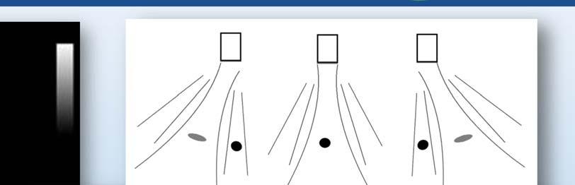
100 Spit Image If the near shadow is in the center of the probe, the ultrasound beam is splitted in two, resulting in two apparent apertures


101 Spilt image Caused by a near shadow in the middle of the probe footprint

102 Enhancement


103 Enhancement
12/26/2017. Alberto Ardon M.D.
 Alberto Ardon M.D. 1 Preparatory Work Ultrasound Physics http://www.nysora.com/mobile/regionalanesthesia/foundations-of-us-guided-nerve-blockstechniques/index.1.html Basic Ultrasound Handling https://www.youtube.com/watch?v=q2otukhrruc
The Physics of Echo. The Physics of Echo. The Physics of Echo Is there pericardial calcification? 9/30/13
 Basic Ultrasound Physics Kirk Spencer MD Speaker has no disclosures to make Sound Audible range 20Khz Medical ultrasound Megahertz range Advantages of imaging with ultrasound Directed as a beam Tomographic
The physics of ultrasound. Dr Graeme Taylor Guy s & St Thomas NHS Trust
 The physics of ultrasound Dr Graeme Taylor Guy s & St Thomas NHS Trust Physics & Instrumentation Modern ultrasound equipment is continually evolving This talk will cover the basics What will be covered?
Artifacts. Artifacts. Causes. Imaging assumptions. Common terms used to describe US images. Common terms used to describe US images
 Artifacts Artifacts Chapter 20 What are they? Simply put they are an error in imaging These artifacts include reflections that are: not real incorrect shape, size or position incorrect brightness displayed
Optimisation of Image Acquisition Bordeaux 16th November J.S. McGhie W.B. Vletter R. Frowijn No disclosures
 Optimisation of Image Acquisition Bordeaux 16th November 2016 J.S. McGhie W.B. Vletter R. Frowijn No disclosures Image optimisation: The Echo machine It looks difficult to drive an echo machine!! Some
Ultrasound & Artifacts
 ISSN 2005-7881 Journal of Neurosonology 3(Suppl. 2):1-17, 2011 Ultrasound & Artifacts Siryung Han The Catholic University of Korea Artifacts False image- echoes without anatomic correlate US image dose
Lesson 06: Pulse-echo Imaging and Display Modes. These lessons contain 26 slides plus 15 multiple-choice questions.
 Lesson 06: Pulse-echo Imaging and Display Modes These lessons contain 26 slides plus 15 multiple-choice questions. These lesson were derived from pages 26 through 32 in the textbook: ULTRASOUND IMAGING
Ultrasound Physics. History: Ultrasound 2/13/2019. Ultrasound
 Ultrasound Physics History: Ultrasound Ultrasound 1942: Dr. Karl Theodore Dussik transmission ultrasound investigation of the brain 1949-51: Holmes and Howry subject submerged in water tank to achieve
Ultrasound Imaging Ultr Michael Dadd 2007
 Ultrasound Imaging Ultrasound Physics & Instrumentation - Recommended Reading 1. Diagnostic Ultrasound: Principles and Instruments (7th Ed) Frederick W Kremkau W B Saunders Company 2. Applied Physics &
Chapter 4. Pulse Echo Imaging. where: d = distance v = velocity t = time
 Chapter 4 Pulse Echo Imaging Ultrasound imaging systems are based on the principle of pulse echo imaging. These systems require the use of short pulses of ultrasound to create two-dimensional, sectional
Lesson 06: Pulse-echo Imaging and Display Modes. This lesson contains 22 slides plus 15 multiple-choice questions.
 Lesson 06: Pulse-echo Imaging and Display Modes This lesson contains 22 slides plus 15 multiple-choice questions. Accompanying text for the slides in this lesson can be found on pages 26 through 32 in
Answer: TGC is needed to amplify echoes from deeper structures so that they appear as bright as similar structures located at more shallow depths.
 Q47. When performing a sonogram why the sonographer needs to use the TGC? TGC is needed to amplify echoes from deeper structures so that they appear as bright as similar structures located at more shallow
Lesson 02: Sound Wave Production. This lesson contains 24 slides plus 11 multiple-choice questions.
 Lesson 02: Sound Wave Production This lesson contains 24 slides plus 11 multiple-choice questions. Accompanying text for the slides in this lesson can be found on pages 2 through 7 in the textbook: ULTRASOUND
Physics of ultrasound
 1 Physics of ultrasound Basic principles Nature of ultrasound Sound = longitudinal, mechanical wave particles move parallel to direction of travel Audible sound < 20 khz Ultrasound > 20 khz Sound cannot
Sonic Distance Sensors
 Sonic Distance Sensors Introduction - Sound is transmitted through the propagation of pressure in the air. - The speed of sound in the air is normally 331m/sec at 0 o C. - Two of the important characteristics
3. Ultrasound Imaging(2)
") 3. Ultrasound Imaging(2) Lecture 13, 14 Medical Imaging Systems Jae Gwan Kim, Ph.D. jaekim@gist.ac.kr, X 2220 Department of BioMedical Science and Engineering Gwangju Institute of Sciences and Technology
3. Ultrasound Imaging(2) Lecture 13, 14 Medical Imaging Systems Jae Gwan Kim, Ph.D. jaekim@gist.ac.kr, X 2220 Department of BioMedical Science and Engineering Gwangju Institute of Sciences and Technology
Introduction to Ultrasound Physics
 Introduction to Ultrasound Physics Vassilis Sboros Medical Physics and Cardiovascular Sciences University of Edinburgh Transverse waves Water remains in position Disturbance traverse producing more wave
Lesson 12: Doppler Principles. This lesson contains 50 slides plus 26 multiple-choice questions.
 Lesson 12: Doppler Principles This lesson contains 50 slides plus 26 multiple-choice questions. Accompanying text for the slides in this lesson can be found on pages 59 through 80 in the textbook: DOPPLER
Ultrasonic Linear Array Medical Imaging System
 Ultrasonic Linear Array Medical Imaging System R. K. Saha, S. Karmakar, S. Saha, M. Roy, S. Sarkar and S.K. Sen Microelectronics Division, Saha Institute of Nuclear Physics, 1/AF Bidhannagar, Kolkata-700064.
4 Working With Scan Modes
 4 Working With Scan Modes Scan Modes Overview All of the information in this chapter pertains to live imaging. Many of the controls and functions change when you freeze the scan. For information on using
Ultrasound Bioinstrumentation. Topic 2 (lecture 3) Beamforming
 Beamforming") Ultrasound Bioinstrumentation Topic 2 (lecture 3) Beamforming Angular Spectrum 2D Fourier transform of aperture Angular spectrum Propagation of Angular Spectrum Propagation as a Linear Spatial Filter Free
Ultrasound Bioinstrumentation Topic 2 (lecture 3) Beamforming Angular Spectrum 2D Fourier transform of aperture Angular spectrum Propagation of Angular Spectrum Propagation as a Linear Spatial Filter Free
Medical Imaging (EL582/BE620/GA4426)
") Medical Imaging (EL582/BE620/GA4426) Jonathan Mamou, PhD Riverside Research Lizzi Center for Biomedical Engineering New York, NY jmamou@riversideresearch.org On behalf of Prof. Daniel Turnbull Outline
Medical Imaging (EL582/BE620/GA4426) Jonathan Mamou, PhD Riverside Research Lizzi Center for Biomedical Engineering New York, NY jmamou@riversideresearch.org On behalf of Prof. Daniel Turnbull Outline
Ultrasound Beamforming and Image Formation. Jeremy J. Dahl
 Ultrasound Beamforming and Image Formation Jeremy J. Dahl Overview Ultrasound Concepts Beamforming Image Formation Absorption and TGC Advanced Beamforming Techniques Synthetic Receive Aperture Parallel
Physics of Ultrasound & Doppler. Sang Jae Rhee. MD., PhD. Division of Cardiovascular Medicine Wonkwang University Hospital
 Physics of Ultrasound & Doppler Sang Jae Rhee. MD., PhD. Division of Cardiovascular Medicine Wonkwang University Hospital Classification of Sound Infrasound Audible sound Ultrasound < 20 Hz 20-20,000 Hz
Ultrasound physical principles in today s technology
 Education Ultrasound physical principles in today s technology Brian Starkoff M.App.Sc.(Med. Ultrasound), AMS Holland Park Brisbane Queensland Australia Correspondence to email starkoff@optusnet.com.au
Interaction of Sound and. logarithms. Logarithms continued. Decibels (db) Decibels (db) continued. Interaction of Sound and Media continued
 Decibels (db) continued. Interaction of Sound and Media continued") Interaction of Sound and Media continued Interaction of Sound and Media Chapter 6 As sound travels through a media and interacts with normal anatomical structures its intensity weakens through what is
Interaction of Sound and Media continued Interaction of Sound and Media Chapter 6 As sound travels through a media and interacts with normal anatomical structures its intensity weakens through what is
Echo Artifacts: The Cause and Solution
 Echo Artifacts: The Cause and Solution David Adams, RCS, RDCS, FASE Duke University Medical Center Disclosures None My Happy / Sad ratio 20% Sad 1 st talk on Sunday (post party) Talk about Artifacts Artifacts
(A) 2f (B) 2 f (C) f ( D) 2 (E) 2
 2f (B) 2 f (C) f ( D) 2 (E) 2") 1. A small vibrating object S moves across the surface of a ripple tank producing the wave fronts shown above. The wave fronts move with speed v. The object is traveling in what direction and with what
1. A small vibrating object S moves across the surface of a ripple tank producing the wave fronts shown above. The wave fronts move with speed v. The object is traveling in what direction and with what
Medical Imaging. X-rays, CT/CAT scans, Ultrasound, Magnetic Resonance Imaging
 Medical Imaging X-rays, CT/CAT scans, Ultrasound, Magnetic Resonance Imaging From: Physics for the IB Diploma Coursebook 6th Edition by Tsokos, Hoeben and Headlee And Higher Level Physics 2 nd Edition
Introduction to Medical Engineering (Medical Imaging) Ultrasound Imaging. Ho Kyung Kim Pusan National University
 Ultrasound Imaging. Ho Kyung Kim Pusan National University") Introduction to Medical Engineering (Medical Imaging) Suetens 6 Ultrasound Imaging Ho Kyung Kim Pusan National University Sound Sonic: 20 Hz 20 khz (audible frequency) Subsonic () Ultrasound
Introduction to Medical Engineering (Medical Imaging) Suetens 6 Ultrasound Imaging Ho Kyung Kim Pusan National University Sound Sonic: 20 Hz 20 khz (audible frequency) Subsonic () Ultrasound
Doppler in Obstetrics: book by K Nicolaides, G Rizzo, K Hecher. Chapter on Doppler ultrasound: principles and practice by Colin Deane
 Doppler in Obstetrics: book by K Nicolaides, G Rizzo, K Hecher Chapter on Doppler ultrasound: principles and practice by Colin Deane INTRODUCTION Competent use of Doppler ultrasound techniques requires
Architecture of Quality Imaging Mary K. Henne, MS, CNMT, RDMS, RVT Ultrasound Education Specialist GE Healthcare
 Architecture of Quality Imaging Mary K. Henne, MS, CNMT, RDMS, RVT Ultrasound Education Specialist GE Healthcare 2 DOC1292532 Architecture of Quality Imaging Agile Acoustic Architecture E-Series and XDclear
Image Optimization: The Sonographer s Responsibility. Prepared by Cathy Daniels, EdD, RTR, RDMS, RDCS, RVT
 Image Optimization: The Sonographer s Responsibility Prepared by Cathy Daniels, EdD, RTR, RDMS, RDCS, RVT Image Optimization: The Sonographer s Responsibility Cathy Daniels, EdD, RTR, RDMS, RDCS, RVT Disclosure
SONOGRAPHIC PHYSICS, INSTRUMENTATION & DOPPLER REVIEW Part 3
 SONOGRAPHIC PHYSICS, INSTRUMENTATION & DOPPLER REVIEW 2012 Part 3 1 Doppler Imaging 2 DOPPLER TRANSDUCER SAME FREQUENCY During Doppler operation, the reflected sound has the same frequency as the transmitted
INTRODUCTION. Have applications for imaging, detection and navigation.
 ULTRASONICS INTRODUCTION The word ultrasonic combines the Latin roots ultra - beyond sonic - sound. Having frequencies above the audible range i.e. above 20000Hz Have applications for imaging, detection
Understanding How Frequency, Beam Patterns of Transducers, and Reflection Characteristics of Targets Affect the Performance of Ultrasonic Sensors
 Characteristics of Targets Affect the Performance of Ultrasonic Sensors By Donald P. Massa, President and CTO of Massa Products Corporation Overview of How an Ultrasonic Sensor Functions Ultrasonic sensors
Spectral Distance Amplitude Control for Ultrasonic Inspection of Composite Components
 ECNDT 26 - Mo.2.6.4 Spectral Distance Amplitude Control for Ultrasonic Inspection of Composite Components Uwe PFEIFFER, Wolfgang HILLGER, DLR German Aerospace Center, Braunschweig, Germany Abstract. Ultrasonic
CHAPTER 1 INTRODUCTION
 CHAPTER 1 INTRODUCTION Spatial resolution in ultrasonic imaging is one of many parameters that impact image quality. Therefore, mechanisms to improve system spatial resolution could result in improved
Pass Ultrasound Physics Exam
 Pass Ultrasound Physics Exam Match the Answers By Mansoor Khan MBBS, RDMS, RDCS 1 Copyright 2014 Blue Cube Venture, LLC All rights reserved. The Pass Ultrasound Physics Exam Match the Answers is protected
PHYSICS 102N Spring Week 6 Oscillations, Waves, Sound and Music
 PHYSICS 102N Spring 2009 Week 6 Oscillations, Waves, Sound and Music Oscillations Any process that repeats itself after fixed time period T Examples: Pendulum, spring and weight, orbits, vibrations (musical
Photomultiplier Tube
 Nuclear Medicine Uses a device known as a Gamma Camera. Also known as a Scintillation or Anger Camera. Detects the release of gamma rays from Radionuclide. The radionuclide can be injected, inhaled or
Physics in Modern Medicine Fall 2010
 Physics in Modern Medicine Fall 2010 Homework #3 Chapter 3 Lasers in Medicine Questions Q3.1 Absorption in melanin increases with decreasing wavelength, and has a maximum, according to figure 3.23 in the
ATS 351 Lecture 9 Radar
 ATS 351 Lecture 9 Radar Radio Waves Electromagnetic Waves Consist of an electric field and a magnetic field Polarization: describes the orientation of the electric field. 1 Remote Sensing Passive vs Active
Quick Reference Guide
 siemens.com/nx3 Quick Reference Guide ACUSON NX3 Series Contents 2 System Overview 3 Getting Started 8 2D Mode and M-mode 12 Color and Spectral Doppler 24 Measurements and Calculations 38 Text, Arrows
Wave Review Questions Updated
 Name: Date: 1. Which type of wave requires a material medium through which to travel? 5. Which characteristic is the same for every color of light in a vacuum? A. radio wave B. microwave C. light wave
ACOUSTIC MICRO IMAGING ANALYSIS METHODS FOR 3D PACKAGES
 ACOUSTIC MICRO IMAGING ANALYSIS METHODS FOR 3D PACKAGES Janet E. Semmens Sonoscan, Inc. Elk Grove Village, IL, USA Jsemmens@sonoscan.com ABSTRACT Earlier studies concerning evaluation of stacked die packages
Lecture 19. Ultrasound Imaging
 Lecture 19 Ultrasound Imaging Contents 1. Introduction 2. Ultrasound and its generation 3. Wave propagation in the matter 4. Data acquisition (A, B, M and Doppler model) 5. Imaging reconstruction (5 steps)
A SHEAR WAVE TRANSDUCER ARRAY FOR REAL-TIME IMAGING. R.L. Baer and G.S. Kino. Edward L. Ginzton Laboratory Stanford University Stanford, CA 94305
 A SHEAR WAVE TRANSDUCER ARRAY FOR REAL-TIME IMAGING R.L. Baer and G.S. Kino Edward L. Ginzton Laboratory Stanford University Stanford, CA 94305 INTRODUCTION In this paper we describe a contacting shear
Chapter 17 Waves in Two and Three Dimensions
 Chapter 17 Waves in Two and Three Dimensions Slide 17-1 Chapter 17: Waves in Two and Three Dimensions Concepts Slide 17-2 Section 17.1: Wavefronts The figure shows cutaway views of a periodic surface wave
The Middle East Distributor for AMBISEA Technology Corp. Electro-Medical Product Line
 The Middle East Distributor for AMBISEA Technology Corp. Electro-Medical Product Line AV-9100 Single Channel ECG 1 2 AV-9300 3-Channels ECG 3 4 5 AV-9000B Multi-Parameter Patient Monitor 6 7 8 AV-9000C
SODAR- sonic detecting and ranging
 Active Remote Sensing of the PBL Immersed vs. remote sensors Active vs. passive sensors RADAR- radio detection and ranging WSR-88D TDWR wind profiler SODAR- sonic detecting and ranging minisodar RASS RADAR
Session: 2A NEW ULTRASOUND SYSTEMS Chair: H. Ermert University of Bochum 2A-1 10:30 a.m.
 Session: 2A NEW ULTRASOUND SYSTEMS Chair: H. Ermert University of Bochum 2A-1 10:30 a.m. TISSUE HARMONIC IMAGING WITH IMPROVED TEMPORAL RESOLUTION D. J. NAPOLITANO*, C. H. CHOU, G. W. MCLAUGHLIN, T. L.
Nuove tecnologie per ecografia ad ultrasuoni: da 2D a 4D
 DINFO Dipartimento di Ingegneria dell Informazione Department of Information Engineering Nuove tecnologie per ecografia ad ultrasuoni: da 2D a 4D Piero Tortoli Microelectronics Systems Design Lab 1 Introduction
Ques on (2): [18 Marks] a) Draw the atrial synchronous Pacemaker block diagram and explain its operation. Benha University June 2013
![Ques on (2): [18 Marks] a) Draw the atrial synchronous Pacemaker block diagram and explain its operation. Benha University June 2013](/thumbs/87/96832478.jpg "Ques on (2): [18 Marks] a) Draw the atrial synchronous Pacemaker block diagram and explain its operation. Benha University June 2013") Benha University June 2013 Benha Faculty of Engineering Electrical Department Hospital Instrumentations (E472) 4 Th year (control) Dr.Waleed Abdel Aziz Salem Time: 3 Hrs Answer the following questions.
Benha University June 2013 Benha Faculty of Engineering Electrical Department Hospital Instrumentations (E472) 4 Th year (control) Dr.Waleed Abdel Aziz Salem Time: 3 Hrs Answer the following questions.
Ultrasound Physics and Instrumentation, 5e Chapter 7: Level 1 Quiz Answers. 1) Which of the following is stated in the introduction of the chapter?
 Which of the following is stated in the introduction of the chapter?") Ultrasound Physics and Instrumentation, 5e Chapter 7: Level 1 Quiz Answers 1) Which of the following is stated in the introduction of the chapter? a) Because of the importance of Doppler, this chapter
Ultrasound Physics and Instrumentation, 5e Chapter 7: Level 1 Quiz Answers 1) Which of the following is stated in the introduction of the chapter? a) Because of the importance of Doppler, this chapter
An Overview Algorithm to Minimise Side Lobes for 2D Circular Phased Array
 An Overview Algorithm to Minimise Side Lobes for 2D Circular Phased Array S. Mondal London South Bank University; School of Engineering 103 Borough Road, London SE1 0AA More info about this article: http://www.ndt.net/?id=19093
Lab 2. Logistics & Travel. Installing all the packages. Makeup class Recorded class Class time to work on lab Remote class
 Lab 2 Installing all the packages Logistics & Travel Makeup class Recorded class Class time to work on lab Remote class Classification of Sensors Proprioceptive sensors internal to robot Exteroceptive
Physics B Waves and Sound Name: AP Review. Show your work:
 Physics B Waves and Sound Name: AP Review Mechanical Wave A disturbance that propagates through a medium with little or no net displacement of the particles of the medium. Parts of a Wave Crest: high point
MAKING TRANSIENT ANTENNA MEASUREMENTS
 MAKING TRANSIENT ANTENNA MEASUREMENTS Roger Dygert, Steven R. Nichols MI Technologies, 1125 Satellite Boulevard, Suite 100 Suwanee, GA 30024-4629 ABSTRACT In addition to steady state performance, antennas
EENG473 Mobile Communications Module 3 : Week # (12) Mobile Radio Propagation: Small-Scale Path Loss
 Mobile Radio Propagation: Small-Scale Path Loss") EENG473 Mobile Communications Module 3 : Week # (12) Mobile Radio Propagation: Small-Scale Path Loss Introduction Small-scale fading is used to describe the rapid fluctuation of the amplitude of a radio
EENG473 Mobile Communications Module 3 : Week # (12) Mobile Radio Propagation: Small-Scale Path Loss Introduction Small-scale fading is used to describe the rapid fluctuation of the amplitude of a radio
CONTACT LASER ULTRASONIC EVALUATION OF CONSTRUCTION MATERIALS
 CONTACT LASER ULTRASONIC EVALUATION OF CONSTRUCTION MATERIALS Alexander A.KARABUTOV 1, Elena V.SAVATEEVA 2, Alexei N. ZHARINOV 1, Alexander A.KARABUTOV 1 Jr. 1 International Laser Center of M.V.Lomonosov
ABC Math Student Copy
 Page 1 of 17 Physics Week 9(Sem. 2) Name Chapter Summary Waves and Sound Cont d 2 Principle of Linear Superposition Sound is a pressure wave. Often two or more sound waves are present at the same place
Explain what is meant by a photon and state one of its main properties [2]
![Explain what is meant by a photon and state one of its main properties [2]](/thumbs/80/82516318.jpg "Explain what is meant by a photon and state one of its main properties [2]") 1 (a) A patient has an X-ray scan taken in hospital. The high-energy X-ray photons interact with the atoms inside the body of the patient. Explain what is meant by a photon and state one of its main properties....
1 (a) A patient has an X-ray scan taken in hospital. The high-energy X-ray photons interact with the atoms inside the body of the patient. Explain what is meant by a photon and state one of its main properties....
Time Reversal FEM Modelling in Thin Aluminium Plates for Defects Detection
 ECNDT - Poster 39 Time Reversal FEM Modelling in Thin Aluminium Plates for Defects Detection Yago GÓMEZ-ULLATE, Instituto de Acústica CSIC, Madrid, Spain Francisco MONTERO DE ESPINOSA, Instituto de Acústica
Properties and Applications
 Properties and Applications What is a Wave? How is it Created? Waves are created by vibrations! Atoms vibrate, strings vibrate, water vibrates A wave is the moving oscillation Waves are the propagation
27/11/2013' OCEANOGRAPHIC APPLICATIONS. Acoustic Current Meters
 egm502 seafloor mapping lecture 17 water column applications OCEANOGRAPHIC APPLICATIONS Acoustic Current Meters An acoustic current meter is a set of transducers fixed in a frame. Acoustic current meters
Fundamentals of Music Technology
 Fundamentals of Music Technology Juan P. Bello Office: 409, 4th floor, 383 LaFayette Street (ext. 85736) Office Hours: Wednesdays 2-5pm Email: jpbello@nyu.edu URL: http://homepages.nyu.edu/~jb2843/ Course-info:
Multi-Element Synthetic Transmit Aperture Method in Medical Ultrasound Imaging Ihor Trots, Yuriy Tasinkevych, Andrzej Nowicki and Marcin Lewandowski
 Multi-Element Synthetic Transmit Aperture Method in Medical Ultrasound Imaging Ihor Trots, Yuriy Tasinkevych, Andrzej Nowicki and Marcin Lewandowski Abstract The paper presents the multi-element synthetic
describe sound as the transmission of energy via longitudinal pressure waves;
 1 Sound-Detailed Study Study Design 2009 2012 Unit 4 Detailed Study: Sound describe sound as the transmission of energy via longitudinal pressure waves; analyse sound using wavelength, frequency and speed
INSPECTION OF THERMAL BARRIERS OF PRIMARY PUMPS WITH PHASED ARRAY PROBE AND PIEZOCOMPOSITE TECHNOLOGY
 INSPECTION OF THERMAL BARRIERS OF PRIMARY PUMPS WITH PHASED ARRAY PROBE AND PIEZOCOMPOSITE TECHNOLOGY J. Poguet Imasonic S.A. France E. Abittan EDF-GDL France Abstract In order to meet the requirements
LINE ARRAY Q&A ABOUT LINE ARRAYS. Question: Why Line Arrays?
 Question: Why Line Arrays? First, what s the goal with any quality sound system? To provide well-defined, full-frequency coverage as consistently as possible from seat to seat. However, traditional speaker
Theory and Applications of Frequency Domain Laser Ultrasonics
 1st International Symposium on Laser Ultrasonics: Science, Technology and Applications July 16-18 2008, Montreal, Canada Theory and Applications of Frequency Domain Laser Ultrasonics Todd W. MURRAY 1,
Key Physics and Doppler Principles
 Key Physics and Doppler Principles Robert A. Levine, MD, FACE, ECNU Thyroid Center of New Hampshire Geisel School of Medicine at Dartmouth College AACE/ACE Advanced Neck Ultrasound Training Course Disclosures:
Fig. 1
 PhysicsAndMathsTutor.com 1 1. Fig. 1 shows data for the intensity of a parallel beam of X-rays after penetration through varying thicknesses of a material. intensity / MW m 2 thickness / mm 0.91 0.40 0.69
Cardiac MR. Dr John Ridgway. Leeds Teaching Hospitals NHS Trust, UK
 Cardiac MR Dr John Ridgway Leeds Teaching Hospitals NHS Trust, UK Cardiac MR Physics for clinicians: Part I Journal of Cardiovascular Magnetic Resonance 2010, 12:71 http://jcmr-online.com/content/12/1/71
Multi-spectral acoustical imaging
 Multi-spectral acoustical imaging Kentaro NAKAMURA 1 ; Xinhua GUO 2 1 Tokyo Institute of Technology, Japan 2 University of Technology, China ABSTRACT Visualization of object through acoustic waves is generally
Waves transfer energy NOT matter Two categories of waves Mechanical Waves require a medium (matter) to transfer wave energy Electromagnetic waves no
 to transfer wave energy Electromagnetic waves no") 1 Waves transfer energy NOT matter Two categories of waves Mechanical Waves require a medium (matter) to transfer wave energy Electromagnetic waves no medium required to transfer wave energy 2 Mechanical
1 Waves transfer energy NOT matter Two categories of waves Mechanical Waves require a medium (matter) to transfer wave energy Electromagnetic waves no medium required to transfer wave energy 2 Mechanical
Ultrasonic Testing using a unipolar pulse
 Ultrasonic Testing using a unipolar pulse by Y. Udagawa* and T. Shiraiwa** *Imaging Supersonic Laboratories Co.,Ltd. 12-7 Tezukayamanakamachi Nara Japan 63163 1. Abstract Krautkramer Japan Co.,Ltd. 9-29
PHYS102 Previous Exam Problems. Sound Waves. If the speed of sound in air is not given in the problem, take it as 343 m/s.
 PHYS102 Previous Exam Problems CHAPTER 17 Sound Waves Sound waves Interference of sound waves Intensity & level Resonance in tubes Doppler effect If the speed of sound in air is not given in the problem,
Doppler Ultrasound. Amanda Watson.
 Doppler Ultrasound Amanda Watson amanda.watson1@nhs.net Before we start Why does blood appear black on a B-mode image? B-mode echoes vs. Doppler echoes In B-Mode we are concerned with the position and
Diffraction. Interference with more than 2 beams. Diffraction gratings. Diffraction by an aperture. Diffraction of a laser beam
 Diffraction Interference with more than 2 beams 3, 4, 5 beams Large number of beams Diffraction gratings Equation Uses Diffraction by an aperture Huygen s principle again, Fresnel zones, Arago s spot Qualitative
Ground Penetrating Radar
 Ground Penetrating Radar Begin a new section: Electromagnetics First EM survey: GPR (Ground Penetrating Radar) Physical Property: Dielectric constant Electrical Permittivity EOSC 350 06 Slide Di-electric
Biomedical. Measurement and Design ELEC4623/ELEC9734. Electrical Safety and Performance Standards
 Biomedical Instrumentation, Measurement and Design ELEC4623/ELEC9734 Electrical Safety and Performance Standards Contents Physiological Effects of Electrical Currents Safety Standards for Medical Instrumentation
Waves-Wave Behaviors
 1. While playing, two children create a standing wave in a rope, as shown in the diagram below. A third child participates by jumping the rope. What is the wavelength of this standing wave? 1. 2.15 m 2.
Principles of Ultrasound Imaging Image Optimization
 Principles of Ultrasound Imaging Image Optimization Robert A. Levine, MD, FACE, ECNU Thyroid Center of New Hampshire Geisel School of Medicine at Dartmouth College Disclosures: No relevant financial or
COMPUTER PHANTOMS FOR SIMULATING ULTRASOUND B-MODE AND CFM IMAGES
 Paper presented at the 23rd Acoustical Imaging Symposium, Boston, Massachusetts, USA, April 13-16, 1997: COMPUTER PHANTOMS FOR SIMULATING ULTRASOUND B-MODE AND CFM IMAGES Jørgen Arendt Jensen and Peter
1. Transverse Waves: the particles in the medium move perpendicular to the direction of the wave motion
 Mechanical Waves Represents the periodic motion of matter e.g. water, sound Energy can be transferred from one point to another by waves Waves are cyclical in nature and display simple harmonic motion
CHAPTER 12 SOUND ass/sound/soundtoc. html. Characteristics of Sound
 CHAPTER 12 SOUND http://www.physicsclassroom.com/cl ass/sound/soundtoc. html Characteristics of Sound Intensity of Sound: Decibels The Ear and Its Response; Loudness Sources of Sound: Vibrating Strings
EMBEDDED DOPPLER ULTRASOUND SIGNAL PROCESSING USING FIELD PROGRAMMABLE GATE ARRAYS
 EMBEDDED DOPPLER ULTRASOUND SIGNAL PROCESSING USING FIELD PROGRAMMABLE GATE ARRAYS Diaa ElRahman Mahmoud, Abou-Bakr M. Youssef and Yasser M. Kadah Biomedical Engineering Department, Cairo University, Giza,
4.6 Waves Waves in air, fluids and solids Transverse and longitudinal waves
 4.6 Waves Wave behaviour is common in both natural and man-made systems. Waves carry energy from one place to another and can also carry information. Designing comfortable and safe structures such as bridges,
ECHO-CANCELLATION IN A SINGLE-TRANSDUCER ULTRASONIC IMAGING SYSTEM
 ECHO-CANCELLATION IN A SINGLE-TRANSDUCER ULTRASONIC IMAGING SYSTEM Johan Carlson a,, Frank Sjöberg b, Nicolas Quieffin c, Ros Kiri Ing c, and Stéfan Catheline c a EISLAB, Dept. of Computer Science and
Chapter 16 Light Waves and Color
 Chapter 16 Light Waves and Color Lecture PowerPoint Copyright The McGraw-Hill Companies, Inc. Permission required for reproduction or display. What causes color? What causes reflection? What causes color?
Lecture 6 SIGNAL PROCESSING. Radar Signal Processing Dr. Aamer Iqbal Bhatti. Dr. Aamer Iqbal Bhatti
 Lecture 6 SIGNAL PROCESSING Signal Reception Receiver Bandwidth Pulse Shape Power Relation Beam Width Pulse Repetition Frequency Antenna Gain Radar Cross Section of Target. Signal-to-noise ratio Receiver
Introductory Physics, High School Learning Standards for a Full First-Year Course
 Introductory Physics, High School Learning Standards for a Full First-Year Course I. C ONTENT S TANDARDS 4.1 Describe the measurable properties of waves (velocity, frequency, wavelength, amplitude, period)
REAL-TIME B-SCAN ULTRASONIC IMAGING USING A DIGITAL PHASED. Robert Dunki-Jacobs and Lewis Thomas General Electric Company Schenectady, New York, 12301
 REAL-TIME B-SCAN ULTRASONIC IMAGING USING A DIGITAL PHASED ARRAY SYSTEM FOR NDE Robert Dunki-Jacobs and Lewis Thomas General Electric Company Schenectady, New York, 12301 INTRODUCTION Phased array systems
MODULE P6: THE WAVE MODEL OF RADIATION OVERVIEW
 OVERVIEW Wave behaviour explains a great many phenomena, both natural and artificial, for all waves have properties in common. The first topic introduces a basic vocabulary for describing waves. Reflections
Chapter 2 Channel Equalization
 Chapter 2 Channel Equalization 2.1 Introduction In wireless communication systems signal experiences distortion due to fading [17]. As signal propagates, it follows multiple paths between transmitter and
Choosing an Ultrasonic Sensor for Ultrasonography
 Sensors & Transducers ISSN 1726-5479 E\,)6$ http://www.sensorsportal.com Choosing an Ultrasonic Sensor for Ultrasonography Ihor TROTS, Andrzej NOWICKI and Jerzy LITNIEWSKI Institute of Fundamental Technological
Three-dimensional investigation of buried structures with multi-transducer parametric sub-bottom profiler as part of hydrographical applications
 Three-dimensional investigation of buried structures with multi-transducer parametric sub-bottom profiler as part Jens LOWAG, Germany, Dr. Jens WUNDERLICH, Germany, Peter HUEMBS, Germany Key words: parametric,